Projects

10 Tips for Precision Sheet Metal Fabrication?

Precision sheet metal fabrication demands more than accurate cutting and modern equipment. It requires disciplined decisions at every stage, from interpreting drawings to inspecting the finished part. A small error in bend allowance can shift a hole by several millimeters. That difference may prevent an assembly from fitting.

Experienced fabricators know that quality begins before the first sheet reaches the laser bed. Material thickness, alloy condition, grain direction, and surface requirements must be confirmed. Clear drawings and current revision files reduce costly misunderstandings. During forming, calibrated press brakes, suitable tooling, and careful springback control help maintain repeatable angles. Sharp edges should be removed without damaging nearby surfaces. Small details matter.

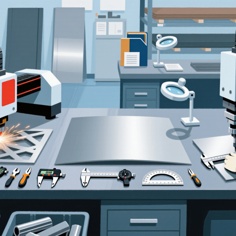
Inspection should combine practical judgment with reliable measurement. Digital calipers, height gauges, angle gauges, and documented first-article checks provide useful evidence. Material certificates and inspection records also strengthen traceability. Still, no workshop is perfect. A rushed setup, an overlooked burr, or an old drawing can create an avoidable problem. That weakness deserves honest review, not excuses.

The ten tips in this guide focus on dependable methods used by skilled fabrication teams. They address design communication, material selection, cutting, bending, finishing, quality control, and production consistency. Some recommendations may seem basic. They are often where failures begin. Careful preparation, realistic tolerances, and open communication can turn a promising design into a precise, functional component. Accuracy is built through habits. And habits require continual checking.
10 Tips for Precision Sheet Metal Fabrication?

Define Precision Requirements with ±0.005 in Tolerances and Datum Control

10 Tips for Precision Sheet Metal Fabrication

Define precision requirements before cutting begins. A ±0.005 in tolerance sounds clear, but it needs a reference. Establish primary, secondary, and tertiary datums on the drawing. These surfaces guide setup, inspection, and assembly. Without datum control, a part may pass individual measurements yet fail when installed.

Tip 1:

Dimension from functional datums, not convenient edges. Edges can shift after bending, deburring, or forming.

Tip 2:

Review tolerance stacks before releasing the design. Hole locations, bend angles, material thickness, and flatness can combine into unexpected movement. On the shop floor, I have seen accurate features create a poor assembly because their references were inconsistent. That mistake is easy to miss. Use a clear GD&T scheme when feature relationships matter. Specify position, profile, and flatness only where they protect function. Excessive tight tolerances increase cost without improving performance.

Tip 3:

Confirm process capability with trial parts and inspection data. Record actual results, not only nominal settings. Temperature, grain direction, tool wear, and springback can influence a ±0.005 in requirement. Use calibrated gauges, height stands, or coordinate measurement equipment suited to the feature. Recheck the datum setup during inspection. A perfect reading from the wrong datum is still unreliable. I sometimes find that a broader tolerance would work better after reviewing the real assembly, so precision should be justified, not assumed.

Match Material and Gauge to 5052 Aluminum or 304 Stainless Steel

Precision sheet metal fabrication starts with the right alloy, not the cutting program. For formed enclosures, 5052 aluminum offers low density, strong corrosion resistance, and reliable bendability. ASM Handbook data lists aluminum density near 2.68 g/cm³, compared with roughly 8.0 g/cm³ for 304 stainless steel. That difference can reduce part weight substantially. However, 5052 can show visible tool marks and springback. Expect some adjustment.

Tip: Select 5052 when weight, forming, and outdoor exposure matter. Confirm the temper, because H32 and annealed material bend differently. Choose gauge by load, span, and dent resistance, not appearance alone. A thin panel may pass inspection but fail during assembly.

304 stainless steel suits demanding interiors, wet environments, and applications requiring higher stiffness. World Stainless reported approximately 58.4 million tonnes of global stainless steel production in 2023, showing the material’s broad industrial use. 304 work-hardens quickly, so sharp tools and repeated forming passes can create cracks. Its density also makes handling and shipping more demanding. Small details matter.

Tip: Use a larger inside bend radius for 304, and verify grain direction before production. For 5052, allow for springback during brake setup. ASTM B209 and ASTM A240 provide useful material and dimensional references, but supplier certificates still need review. Gauge charts are convenient, not perfect. Prototype one part, measure the bend angle, then correct the tooling before a full run.

10 Tips for Precision Sheet Metal Fabrication? - Match Material and Gauge to 5052 Aluminum or 304 Stainless Steel

No. Fabrication Tip 5052 Aluminum 304 Stainless Steel Recommended Practice
1 Define the service environment Good corrosion resistance, especially in marine and mildly corrosive environments; not ideal for highly alkaline conditions. Strong general corrosion resistance; suitable for many indoor, food-processing, and chemical-service applications. Select the alloy based on moisture, chemicals, temperature, and exposure—not appearance alone.
2 Match the sheet gauge to the load Lower density, approximately 2.68 g/cm³, helps reduce part weight but generally requires adequate thickness for stiffness. Higher density, approximately 8.00 g/cm³, provides a heavier and often more rigid part at the same thickness. Use structural calculations or testing to determine thickness; do not select gauge only by material type.
3 Consider forming behavior 5052-H32 has good formability and is commonly used for bent enclosures, brackets, tanks, and panels. 304 is formable but work-hardens rapidly, increasing forming force and the risk of cracking during severe operations. Use suitable bend radii, controlled tooling, and staged forming for complex shapes.
4 Set the inside bend radius A practical starting point for 5052-H32 is approximately 1.5 times the material thickness for many 90° bends, subject to temper and tooling. A larger inside radius is often beneficial because 304 work-hardens during bending; exact limits depend on thickness and condition. Confirm the minimum radius with the material supplier and perform a trial bend for critical parts.
5 Allow for bend deduction Use a measured K-factor or bend allowance because aluminum springback and forming response vary by temper. Expect more springback and higher forming force than aluminum in many comparable thicknesses. Validate flat-pattern calculations with a first-article sample before releasing production tooling.
6 Choose cutting parameters carefully Laser cutting can produce clean edges, but excessive heat may create a heat-affected zone or distortion in thin sheet. Laser cutting is effective, although heat input, dross, and edge discoloration should be controlled. Tune power, speed, gas, and focus for the selected alloy and thickness; inspect edges on precision features.
7 Prevent galling and contamination Aluminum can pick up embedded particles from shared tooling and may show visible scratches. 304 stainless steel is susceptible to galling during contact and forming if tooling is poorly maintained. Use clean, dedicated or well-maintained tooling, suitable lubricants, and protective films where appropriate.
8 Design holes and slots away from bends Small holes positioned too close to a bend may elongate or distort during forming. Work hardening and higher forming forces can increase distortion near bends and formed features. Keep openings outside the bend-affected zone; when unavoidable, form first and machine afterward.
9 Plan welding and heat control 5052 is readily weldable, but heat can reduce strength in the heat-affected zone of strain-hardened material. 304 is commonly welded, but heat tint and sensitization risks require appropriate procedures and cleaning. Control heat input, distortion, shielding, and post-weld cleaning according to the required service conditions.
10 Verify dimensions and surface finish Check flatness, bend angles, scratches, burrs, and dimensional changes caused by lightweight sheet behavior. Check bend angle, edge condition, heat tint, surface scratches, and burrs, especially when appearance matters. Define measurable tolerances, inspection points, and finish requirements on the drawing before fabrication.

Material note: Actual bend limits, tolerances, forming forces, and welding requirements depend on alloy temper, sheet thickness, tooling, part geometry, and the applicable specification. Confirm production values with the material certificate and a qualified fabrication trial.

Optimize CAD and Bend Allowance for ±0.5° Forming Accuracy

10 Tips for Precision Sheet Metal Fabrication?
Optimize CAD and Bend Allowance for ±0.5° Forming Accuracy

Precision forming starts before the first sheet reaches the press brake. Build the correct material thickness, inside radius, and bend method into the CAD model. A generic K-factor often creates avoidable errors. Test a small coupon, measure the formed angle, and update the bend table with real shop data. Keep the flat pattern linked to the approved model.

Small variables matter. Grain direction can change springback, especially in high-strength sheet. Tool wear, clamping pressure, and temperature may also shift the final angle. Use consistent tooling and verify the back gauge before production. A calibrated digital angle gauge should confirm each setup. For ±0.5° accuracy, measure near the bend, not across a distorted flange.

A practical mistake is trusting software output without checking the first part. I have seen accurate drawings produce poor bends because the material lot differed slightly. Record thickness and hardness when receiving critical sheets. Form a trial piece, inspect both legs, and adjust the bend allowance only when evidence supports it. This approach takes longer at setup. It usually prevents costly rework. Perfect consistency is not automatic. It must be demonstrated.

10 Tips for Precision Sheet Metal Fabrication: CAD and Bend Allowance Impact

Mean bend-angle deviation achieved as key fabrication controls are added

The benchmark uses a nominal 90° bend and reports deviation in degrees. Optimizing the CAD model, validating bend allowance and K-factor values, calibrating tooling, and checking the first article can progressively reduce forming variation toward the ±0.5° accuracy target.

Control Cutting, Forming, and Welding to Limit Kerf and Springback

Precision sheet metal work depends on controlling small changes before they become assembly problems. During cutting, verify material thickness, alloy, and nozzle alignment before production. A narrow, stable kerf protects hole size and edge position. Use test cuts, then measure them with calipers or a coordinate measuring arm. Heat can pull thin panels, especially around dense patterns. Leave practical spacing between features, and avoid assuming the machine’s nominal setting is always accurate. It is not.

Forming demands a realistic bend allowance and inside radius. Springback changes with tensile strength, grain direction, tooling wear, and bend length. Record actual angles from trial pieces, not only from software. Overbending may correct one batch and damage the next. A controlled test coupon helps reveal that difference. Keep tooling clean and support narrow flanges. Small witness marks can expose slipping, though they are easy to overlook during a busy shift.

Welding introduces another kind of movement. Clamp parts without crushing them, use balanced tack welds, and distribute heat across the joint. Short, alternating welds often reduce distortion better than one continuous pass. Let the assembly cool between stages when the procedure allows it. Inspect gap, angle, and flatness after welding, not just bead appearance. My own process reviews have shown an uncomfortable truth: a beautiful weld can still sit on a warped part. Document measurements, revise fixtures, and question tolerances that repeatedly fail in production.

Verify Quality with CMM Inspection and a Minimum CpK of 1.33

Precision sheet metal fabrication depends on controlled details, not visual confidence. A clean bend can still fail a critical tolerance. Inspect drawings for material thickness, bend allowance, datum structure, and geometric tolerances before production begins.

Tip 1: Define measurable acceptance limits.
Tip 2: Confirm the drawing revision at the workstation.

CMM inspection provides reliable dimensional evidence when the setup is controlled. Allow parts to stabilize near the inspection temperature. Clean the surface, use repeatable fixturing, and align the coordinate system to the approved datums. Measure holes, flatness, profiles, and bend locations rather than checking only overall length.

Tip 3: Use a documented inspection plan.
Tip 4: Review measurement-system variation before trusting results.

A CMM cannot correct poor datum selection.

A minimum CpK of 1.33 should support critical dimensions, but only after process stability is demonstrated. Collect representative production data, not selected pieces from a convenient batch. Separate short-term capability from long-term performance. Investigate tool wear, springback, burrs, and temperature shifts when the index drops.

Tip 5: Record CpK with the specification limits and sample size.
Tip 6: React to trends before parts become nonconforming.
In practice, a polished report may hide unstable production. I have seen capable-looking averages fail after a tooling change. CpK is useful evidence, not a substitute for engineering judgment. Keep inspection records traceable to the machine, operator, material lot, and measurement date.